This diagnostics board from Amstrad is the official one used in technical services. It performs a very complete series of tests on the machine to check its status and diagnose possible breakdowns.
A> TEST PCB AMSTRAD PCW 9512
Hardware Images
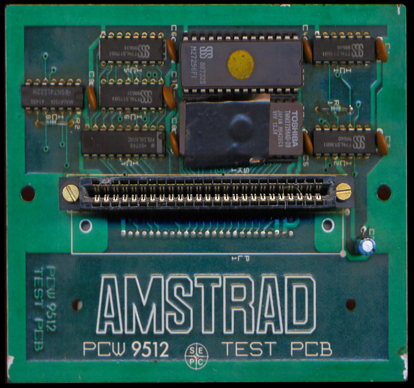
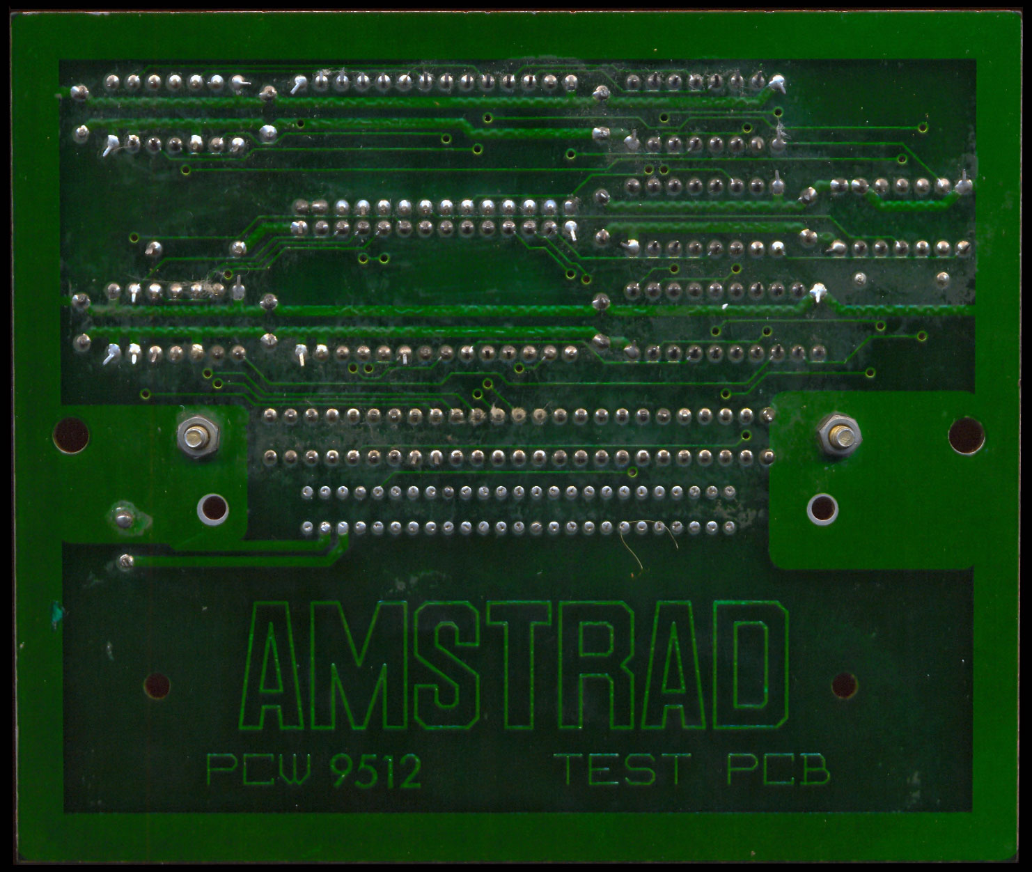
PCB ComponentsPCB SoldersDescription, Context and Service Engineering (9000 Series)
Distributed strictly from **1987-1988** on a confidential and numbered basis to official Amstrad plc workshops, the Amstrad PCW 9512 Test PCB represents the definitive hardware diagnostic tool for the second generation of the office computer range. Although it inherits the maintenance purpose of its predecessor (the 8256 model), this printed circuit board was completely redesigned at the silicon level to interface natively with the profound structural changes introduced in the PCW 9512 motherboard, including the new vertical-page high-definition video subsystem, the stock built-in parallel port, and an expanded memory layout.
The PCW 9512 retained the same critical boot architecture lacking an onboard ROM on its motherboard. When powering on the computer, the Zilog Z80 processor strictly requires the native 3.5-inch floppy disk drive (Drive A:) to inject the boot sector directly into the RAM. In the event of severe system faults that prevented cold booting (such as short circuits on refresh lines or banking page failures), the computer became useless, and technicians could not rely on floppy disks. This workshop Test PCB bypassed the lockdown by physically injecting autonomous diagnostic firmware into the bus, applying the **Bus Overriding / ROM Shadowing** technique to seamlessly take control of the CPU during the exact power-on cycle (boot vector 0000h).
Hardware Architecture and 9512-Specific Logical Testing Routines
The printed circuit board (visible on its component and solder sides) implements advanced control logic optimized to verify the specific hardware modules of the 9000 series:
- RAM Inhibition and EPROM Injection: Upon connecting to the PCW 9512's rear 50-pin expansion bus, the discrete TTL logic integrated on the test card intercepts the CPU memory control signals (
/MREQand/RD). The Test PCB hardware forces an electrical state that blocks and overrides the motherboard's memory chip responses, compelling the Z80 processor to exclusively read the firmware stored in its own physical EPROM chips, whose binary images are preserved in this sheet. - Sweep of the Onboard 512 KB RAM (March Test): Unlike the 8000 series, the PCW 9512 came factory-equipped with a massive bank of 512 KB dynamic RAM. The official firmware injected by the board executes a high-speed alternating binary pattern check loop (hexadecimal sequences
55handAAh). This sweep verifies the integrity of the refresh lines and the stability of the memory cells, mapping errors bit by bit so the technician can identify the exact defective DRAM chip. - Initialization of the High-Resolution Display Controller: The test firmware writes directly to the registers of the new PCW 9512 video controller. By injecting stable geometric synchronism frames into the white-phosphor monitor, the board immediately clarifies whether a blank or distorted screen is due to a digital breakdown on the motherboard or an analog defect in the CRT tube deflection circuits.
- Audit of the Native Centronics Parallel Port: Since the 9512 featured a built-in parallel port on the motherboard for its official daisy-wheel printer, the test interface executes specific testing routines on the Input/Output lines of this port, isolating common failures caused by back-currents from external printing peripherals.
Downloads Section
| Format | Documentation File / ROM Image |
|---|---|
| DSK / ZIP | ROMS (Compressed files in ZIP format) |