
As we get used to a computer model, we find ourselves closer and closer to its limits. Messages like "Out of memory" or "No bytes free" drive any programmer to despair while working hard to solve a complicated task, who will have to fix it with a thorough and deep review of their work, looking for some method that leads to the same result while saving as much memory as possible.
Fortunately for users of an Amstrad PCW 8256 professional computer, the problem is of minor importance; it comes ready out of the box to take a true "giant step," considerably increasing its RAM memory. First of all, it must be clarified that, although the PCW doubles its RAM up to half a megabyte, this memory will not modify at all the characteristics of the Basic programming language delivered with the computer, so if a program fell short on the stock computer, the same will happen after the conversion.
A great application for memory upgrades in these cases is increasing the capacity of the virtual disk or RAM disk. In the specific case of the PCW, the 256Kb expansion is used to increase the capacity of its M: drive from 112 K to 368 Kb. This way, copying files from one disk to another through the virtual disk is done all at once, using the command "PIP M:A:*.*". Therefore, the main advantage of this RAM disk is that it can be used like a conventional disk drive, where there are no mechanical delays due to the absence of a read arm; on the flip side, the virtual disk is exposed to the destruction of all files it contains the moment the computer is turned off.
The expansion discussed below for the PCW 8256 turns it virtually identical to the 8512 model. For this reason, and to avoid diversifying the computer range, Amstrad decided to stop manufacturing the PCW 8256. It would be expected that, with this intention, the price of the official kit marketed by the company would drop considerably, prompting many users of this computer to upgrade it. Although the memory upgrade is extremely simple, even for someone not very well-versed in electronics, it is worth remembering that the moment any screw on the monitor casing was removed, it lost its warranty. In this case, it was better to have it done by an Amstrad technical service, or wait for the warranty to expire.
If we decide to perform the upgrade ourselves, we will need 8 RAM chips of 256 Kb with the designation 41256-15. This sub-designation "-15" indicates that it can work at a maximum speed of 150 nanoseconds or, what is the same, the memories can communicate with the microprocessor at six million times in one second!.
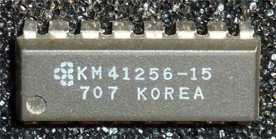 Photo 7
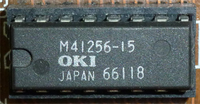 Photo 8
In case you cannot find them, you can choose to buy faster but also more expensive memories. Well, with the 8 integrated circuits on the table, we will need some tools, such as a long Phillips screwdriver.
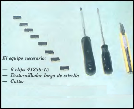 Photo 1
The first step we must follow is to unplug the computer from the mains and wait about five minutes for it to discharge. Next, we will rest the monitor screen on a table (it is advisable to place a towel in between to prevent damage to the screen) and use the screwdriver to remove the six screws fixing the rear casing.
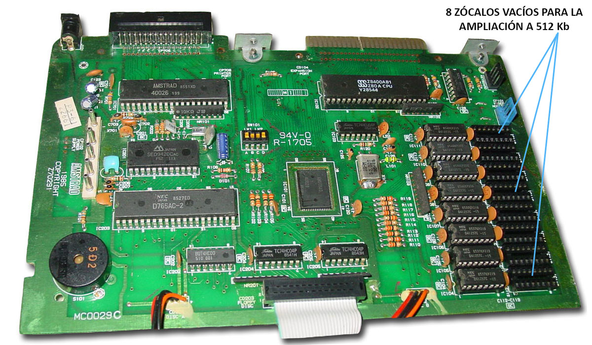
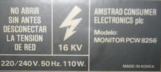 Photo 3
Immediately afterwards, we will lift the casing to expose all the circuitry and focus on the board closest to the disk drive. This is the computer's main circuit board, and on it are the eight empty sockets eagerly awaiting the extra memory. To install the chips, it will not be necessary to remove this board from the central unit, and when positioning them we must ensure that the small notch they feature is correctly placed pointing towards the upper part of the computer; that is, in the same direction as the eight similar integrated circuits located next to the new ones. In most cases, the chips will not slide easily into the sockets, so we must help them by bending their pins slightly inwards, but under no circumstances should we force them into place.
 Sockets
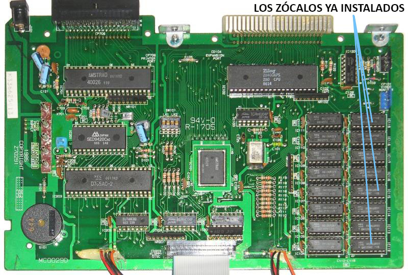 Insertion
Once the 8 chips are placed on the board, let's not claim victory just yet, because the PCW still cannot recognize the new memory configuration. To do this, we must look at a small group of microswitches located in the central part of the board, labeled A, B, C, and D. As the PCW comes from the factory, the switches will be set to ON-OFF-OFF-ON respectively, but we must change the state of switches A and B while keeping C and D the same to convert it into an 8512, meaning that, in the end, it would be set to OFF-ON-OFF-ON. No other configuration should be used, as some can damage the computer.
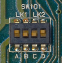 Switches 1
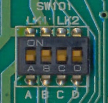 Switches 2
Now we will reconnect the computer to the mains and insert the CP/M operating system (side 2) into drive A:. Let's keep our fingers crossed for a moment until the boot message appears on the screen. Look closely at it, because the size of the M: drive will have changed to 368 Kb. If it hasn't, which would be very strange, something has been connected incorrectly; unplug the computer from the mains again and follow the aforementioned steps once more, verifying that all eight chips are making perfect contact.
- PCWWiki is not responsible for any damage suffered during the handling of any equipment, as this is a guideline and the users who handle the equipment must assume responsibility for any damage caused to them.